Why the Same Formulation Can Run Perfectly on One Extruder and Fail on Another
In plastic compounding and extrusion processing, two different groups often blame each other when production becomes unstable.
Production team“The formulation is too slippery. The screw is spinning but not feeding properly, and the die pressure cannot build. There must be too much external lubricant.”
Formulation engineer“The same formulation ran perfectly on the laboratory extruder. Why does it suddenly show poor plasticization and black specks on the production line? The lubricant is there to reduce viscosity and prevent degradation.”
In many cases, neither side is completely wrong.
The real problem is often a mismatch between screw geometry and the lubrication system.
Two screw parameters are especially important:
L/D ratio — length-to-diameter ratio
Compression ratio — ε
These parameters determine how long the material stays inside the extruder, how strongly it is compressed and sheared, and how much thermal and mechanical energy it receives.
Internal and external lubricants must therefore be selected according to the actual screw geometry — not only according to the polymer formulation.
1. L/D Ratio: The Scale of Residence Time and Accumulated Shear
The L/D ratio is the ratio between the effective screw length and the screw outside diameter.
In practical processing terms, it strongly affects two things:
Residence time and total shear / thermal history.
The longer the effective screw path, the longer the material experiences melting, mixing, friction, heat transfer and shear.
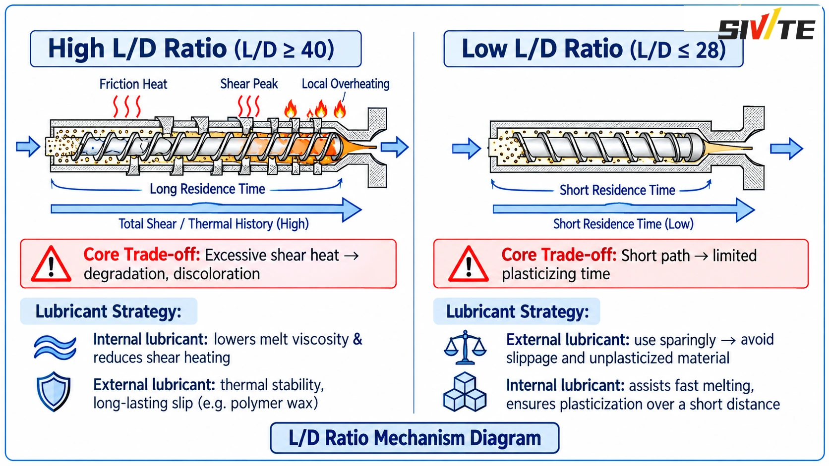
1.1 High L/D Ratio — Typically L/D ≥ 40 or 44
High L/D designs are commonly found in:
- Twin screw compounding lines
- Highly filled compounds
- Devolatilization systems
- Applications requiring intensive dispersion
The advantage is obvious: the material has more processing length available for melting, mixing, venting and homogenization.
But the same advantage also creates the main risk.
The material experiences a much longer shear and thermal history.
If the polymer has high viscosity or poor thermal stability, the second half of the screw can become particularly sensitive to local overheating.
This may result in:
- Polymer degradation
- Yellowing
- Black specks
- Die buildup
- Unstable melt quality
- Melt fracture
Lubricant Strategy for High L/D Systems
Internal lubrication should control shear heating.
An appropriate internal lubricant can reduce intermolecular friction and melt viscosity, helping reduce unnecessary viscous heating during the long processing path.
The objective is not simply to make the melt “slippery.”
It is to keep viscosity and mechanical-energy input within a controllable range.
External lubrication must provide thermal stability and long-lasting interfacial slip.
A long screw path puts greater demands on the durability of the external lubricant.
Lubricants with poor thermal stability or poor compatibility may lose effectiveness too early, migrate, or separate under prolonged heat and shear.
By the time the melt reaches the metering section and die, the protective interfacial lubrication may already be insufficient.
This can promote:
- Die deposits
- Surface defects
- Excessive wall friction
- Unstable flow
For long L/D applications, higher-temperature-resistant lubricant systems such as suitable high-molecular-weight waxes, oxidized polyethylene waxes or carefully selected ester lubricants may offer better stability.
The specific choice still depends on the polymer system.
1.2 Low L/D Ratio — Typically L/D ≤ 28 or 32
Lower L/D designs are commonly used in certain single screw extrusion systems, profile and pipe applications, or processes where the polymer is extremely shear-sensitive.
The processing challenge is almost the opposite.
The material has only a short distance in which to complete:
- Feeding
- Solids conveying
- Compaction
- Melting
- Plasticization
- Pressure generation
The available plasticization time is limited.
Lubricant Strategy for Low L/D Systems
External lubricant must be carefully controlled.
In a short screw, excessive external lubrication can reduce the friction needed between the solid polymer and the barrel wall.
When this happens, the screw may rotate without effectively conveying the material forward.
Typical symptoms include:
- Poor feeding
- Screw slippage
- Output fluctuation
- Unmelted particles
- Pressure instability
Even a relatively small formulation change can become much more obvious on a low L/D machine because the system has less processing distance available to compensate.
Internal lubrication should support rapid and uniform melting.
The objective is to improve polymer-chain mobility without destroying the friction required for stable solids conveying.
A properly selected internal lubricant can help the material reach a uniform melt state within a shorter screw distance.
2. Compression Ratio: The Driver of Compaction and Peak Shear
Compression ratio describes the relationship between the channel volume in the feeding section and the channel volume in the metering section.
In simplified terms, it determines how aggressively the screw compresses the material from a loose solid bed into a dense melt.
It therefore influences:
- Pressure generation
- Compaction intensity
- Melt homogenization
- Peak shear stress
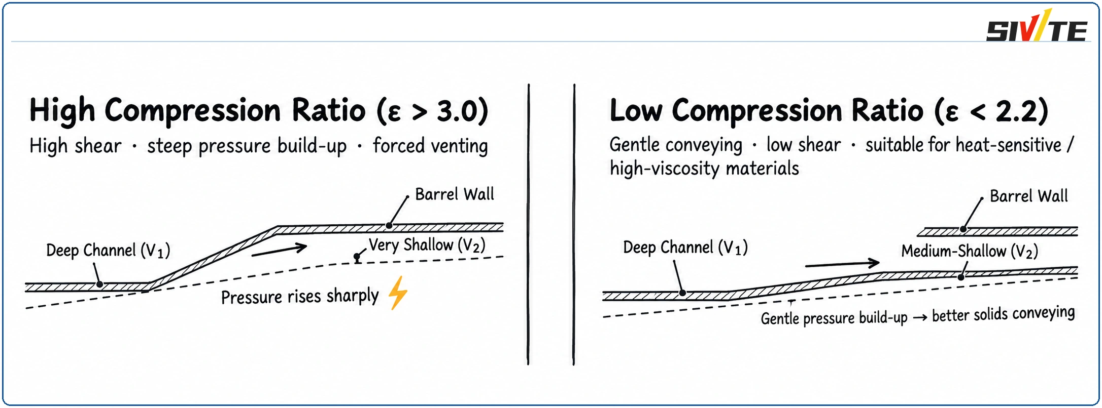
2.1 High Compression Ratio — Typically ε > 3.0
A higher compression ratio may be used where stronger compaction, rapid pressure build-up or intensive melt processing is required.
The transition from the feeding section into the compression zone becomes more aggressive.
As channel volume decreases quickly:
- Pressure rises faster
- Mechanical compression increases
- Wall shear becomes stronger
Lubricant Strategy for High Compression Ratios
External lubricant acts as protection against excessive wall friction.
When the material is heavily compressed against the barrel and screw surfaces, insufficient boundary lubrication can generate substantial frictional heat.
The result may be:
- Local degradation
- Discoloration
- Deposits
- Accelerated screw/barrel wear
A suitable external lubricant can therefore help control interfacial friction.
However, more is not always better.
Under high pressure and high shear, a poorly compatible external lubricant can be pushed out of the polymer matrix.
This can cause migration or plate-out around the die, producing surface marks, deposits or unstable appearance.
The correct approach is to balance lubrication efficiency with polymer compatibility.
2.2 Low Compression Ratio — Typically ε < 2.2
A lower compression ratio provides gentler compaction and lower mechanical shear.
It can be advantageous for certain high-viscosity or highly heat-sensitive materials where aggressive compression would create excessive shear heating.
But the screw also provides less mechanical assistance for conveying and plasticization.
Lubricant Strategy for Low Compression Ratios
External lubricant must not be excessive.
When mechanical compaction is already weak, excessive external lubrication further reduces friction between the material and barrel wall.
The screw may no longer develop enough solids-conveying force.
Symptoms may include:
- Slippage
- Feed instability
- Material backing up
- Output loss
- Incomplete plasticization
Internal lubricant should maintain controlled melt mobility.
The goal is to improve intermolecular movement and melt flow while preserving sufficient conveying friction.
In a low-compression system, the lubricant package must help the polymer process smoothly without making the solids bed excessively slippery.
High L/D
Longer residence time
→ More accumulated shear
→ Higher lubricant thermal-stability requirement
High Compression Ratio
Stronger pressure build-up
→ Higher wall friction
→ More attention to boundary lubrication
Low L/D / Low Compression
Limited processing distance
→ Less tolerance for excessive external lubrication
3. Two Common Production Failures
Problem · Case 1
Laboratory Trial Works, Production Line Turns Yellow and Produces Black Specks
A formulation performs well on a laboratory twin screw extruder with an L/D of 36.
The external lubricant level is 0.5%, and the compound has good appearance.
The same formulation is then transferred to a production extruder with L/D = 44.
Suddenly the production line shows:
- Vent-port instability
- Yellowing
- Occasional black specks
Why?
The longer production screw gives the material significantly more total thermal and shear history.
The original lubricant system was optimized for the shorter laboratory machine.
Under prolonged processing, part of the lubricant system may lose stability or separate earlier than expected.
At the same time, the polymer receives more mechanical energy and may experience higher actual melt temperature.
Corrective Direction
Instead of simply changing the barrel temperature, review both the process and lubricant system.
Possible actions include:
- Reducing unsuitable low-stability wax components
- Selecting a more thermally stable ester or oxidized wax system
- Moderately reducing downstream barrel temperature if actual melt temperature is too high
Problem · Case 2
New Screw Installed, but Output Drops and Feeding Becomes Unstable
A factory replaces a screw to reduce melt yellowing.
The original compression ratio is 3.2.
The new screw has a compression ratio of 2.2.
The barrel temperature settings remain unchanged.
After the replacement:
- The feed zone begins bridging
- Screw conveying becomes unstable
- Output drops by approximately 30%
Why?
The new low-compression screw provides less aggressive solids conveying and pressure development.
However, the existing formulation was designed around the stronger compression characteristics of the previous screw.
The external lubrication level is now too high for the new mechanical system.
The material loses the barrel-wall friction required to establish stable solids conveying.
Corrective Direction
A temporary process adjustment may involve slightly increasing the temperature of the early barrel zones to improve surface adhesion and initial plasticization.
However, the more fundamental solution is to reduce excessive external lubrication and rebalance the formulation for the new screw geometry.
4. A Three-Step Method for Matching Formulation and Extruder
Instead of asking whether the “machine is wrong” or the “formula is wrong,” use the screw geometry as the starting point.
Check the L/D Ratio
A high L/D ratio means longer residence time and greater accumulated shear.
The lubricant system therefore needs better thermal durability, while internal lubrication should help control self-generated shear heat.
A low L/D ratio gives less processing distance, so external lubrication must be controlled carefully and internal lubrication should support rapid melting.
Check the Compression Ratio
A high compression ratio creates stronger pressure build-up and wall friction.
External lubrication may be more important, but lubricant migration and die plate-out must be monitored.
A low compression ratio gives weaker mechanical conveying, so excessive external lubrication can quickly cause slippage and feed instability.
Fine-Tune According to Production Symptoms
If the screw rotates but feeding becomes unstable:
First investigate excessive external lubrication and insufficient solids-barrel friction.
If vent overflow, die deposits or lubricant plate-out appear:
Examine whether high shear is causing phase separation and whether the external lubricant level or compatibility needs adjustment.
Conclusion
The mechanical geometry of the screw defines the physical route through which the polymer must travel.
The lubricant system determines how the material behaves inside that route.
These two cannot be optimized independently.
A formulation that performs perfectly on one extruder may behave completely differently when transferred to another machine with a different L/D ratio, compression ratio or screw configuration.
For stable industrial production, formulation engineers and process engineers need to work from the same mechanical foundation:
Screw geometry + material rheology + lubricant compatibility + actual processing conditions.
Once these relationships are understood, troubleshooting becomes much more systematic — and far less dependent on trial and error.
For related equipment configurations, review our plastic sheet extrusion lines or browse the Technical Blog.