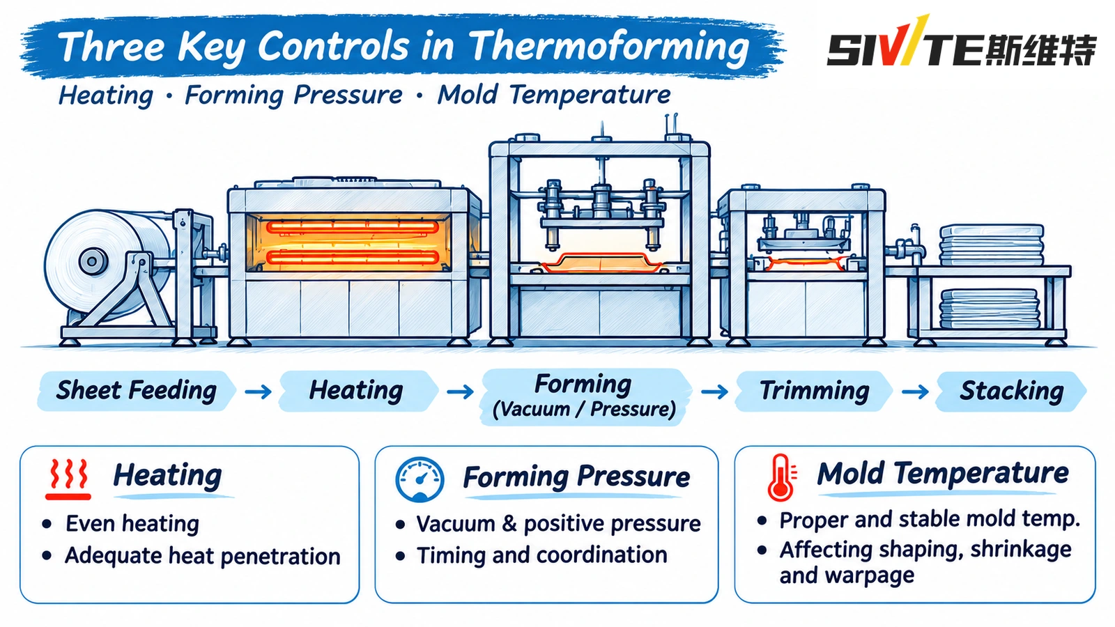
Three process controls decide whether a thermoformed part leaves the mold flat, dimensionally stable and free of webbing.
Picture a line running the same machine, the same mold and the same recipe it ran last week. A new roll of sheet arrives, and the parts start coming out with stretched white marks between the cavities, one corner lifting off the platen, and a wall thickness that reads thin on the same side every cycle. The operator does what most operators do: nudges the heater percentage up a little, then the pressure, then the cooling time. By the end of the shift the recipe on the screen no longer resembles the one that was running well, and nobody can say which change fixed the part — or whether it was fixed at all.
The reason this happens is that heating, forming pressure and mold temperature are not three independent dials. They are three variables in one energy balance. Sheet temperature decides how much the polymer can stretch and how fast it cools afterwards. Forming pressure decides how faithfully that stretch is pushed into the mold surface. Mold temperature decides how quickly the stretched sheet freezes and how much it shrinks on the way. Change one and you have changed the starting conditions for the other two.
- Heating — sets the drawability of the sheet and the window in which the other two controls even matter.
- Forming pressure — sets how much mold detail is reproduced and how wall thickness is distributed.
- Mold temperature — sets shrinkage, warpage and the cooling share of the cycle.
This guide explains how the three controls interact, gives a setting sequence you can run in a shift rather than a week, and ends with a symptom-based troubleshooting matrix so that the next change you make is the right one instead of the fourth one.
1. Why Thermoforming Process Parameters Must Be Tuned Together
Single-variable trial and error fails in thermoforming because every adjustment moves the sheet further along a cooling curve that is already in progress. Raise the sheet temperature by 10 °C and the sheet draws more easily at lower pressure — but if mold temperature is unchanged, the additional heat still has to be removed before ejection. Cooling time is fixed by the recipe, so the part is ejected hotter than before, and it warps after it leaves the machine. The operator sees a new defect, assumes the heating change was wrong, and reverses it, when the real problem was that cooling was never re-matched to the new sheet temperature.
The three controls form a causal chain with one master variable and two followers:
- Mold temperature is the master variable. It defines the heat sink the sheet must reach. Set it first and keep it stable, or every later measurement is taken against a moving reference.
- Sheet temperature is the first follower. It must be high enough to draw and low enough to freeze within the available cooling time at that mold temperature.
- Forming pressure is the second follower. It only has to be high enough to reproduce detail in a sheet that is correctly heated; extra pressure cannot compensate for a cold or uneven sheet.
That hierarchy is why the practical setting order is mold temperature first, heating second, pressure last. Working in the other direction — pressure first, because it is the easiest number to change — produces recipes that work only in the ambient conditions they were tuned in.
2. Heating: Sheet Temperature and Heat Uniformity
What the heater actually controls
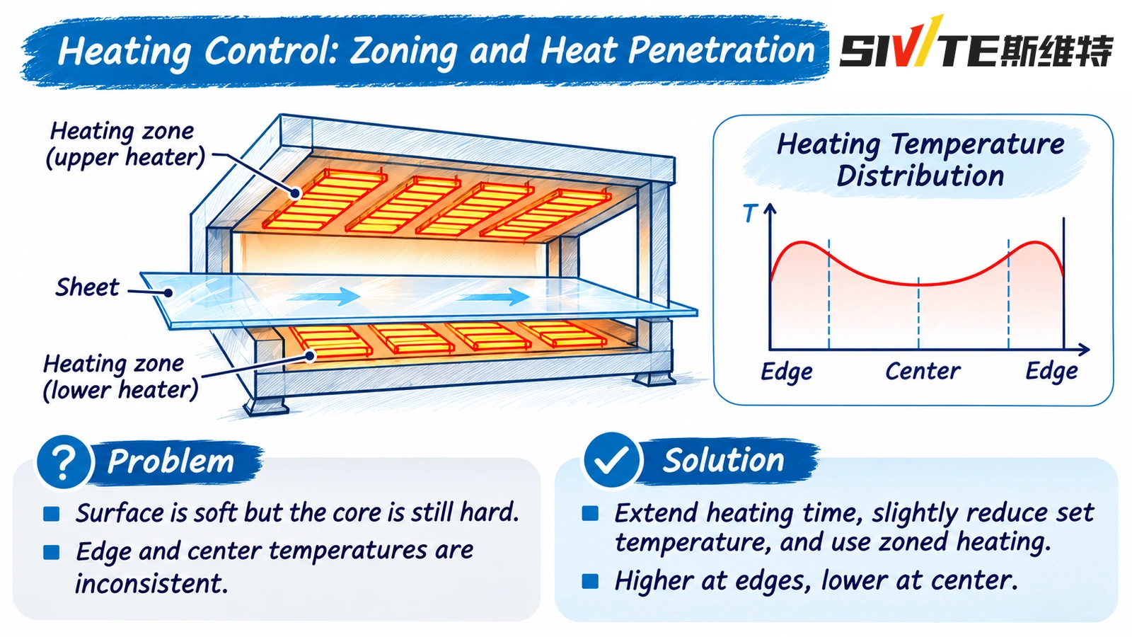
An infrared or ceramic oven does not set a temperature; it delivers a heat flux over time. What the sheet receives depends on emitter power, distance, reflector condition, zone layout, sheet color and surface finish, and the dwell time in the oven. Two machines with identical setpoints can deliver very different sheet temperatures because their reflectors are in different condition. This is the single most common reason a recipe cannot be copied between machines.
What you actually need at the end of heating is a sheet that is above its softening range through the full thickness, with the two surfaces as close in temperature as the process allows. For most amorphous sheet such as PS, PVC or PET the forming window sits roughly between 120 °C and 170 °C at the surface, and for PP it is narrower and higher. Treat those numbers as a starting point to be verified on your machine and material, not as a specification.
Measuring sheet surface temperature, not oven air temperature
Oven air temperature tells you about the oven. Sheet surface temperature tells you about the part. Measure the sheet, on both faces, at several points across the width, immediately after the platen opens.
- Use a contact or infrared pyrometer with the emissivity set for the sheet — typically 0.90 to 0.95 for pigmented and most clear thermoplastics. A pyrometer left at the factory default of 0.95 on a glossy black sheet will read several degrees low.
- Measure top and bottom at the center and both edges, and record the difference rather than a single number. A top-to-bottom difference above roughly 5 to 8 °C is usually visible in the finished part as uneven draw or one-sided thinning.
- Measure at the moment of transfer, not after a delay. The sheet loses heat to the air during transfer, and a reading taken five seconds late will understate the temperature the mold actually saw.
Common heating faults: sagging, hot spots, uneven draw
Most heating problems present as one of three patterns, and each points at a different part of the oven rather than at the recipe.
- Sagging — the sheet bows in the oven before forming. It is caused by heating the sheet past its softening point without support, or by heating the center faster than the edges because the center sits closer to the emitters. Reduce center zone power, add support, or shorten the dwell time and raise the emitter temperature to keep the heat at the surface rather than through the thickness.
- Hot spots — localized glossy or discolored patches, or a part that thins in one place every cycle. Usually a failed emitter, a dirty reflector, or a zone map that does not match the mold layout. Check emitter-by-emitter output with the sheet out of the oven before touching any recipe value.
- Uneven draw — the part forms, but one side is visibly thinner. Often the oven is uniform and the mold is not: asymmetric cooling, an off-center vacuum port, or a plug that is not aligned. Confirm the sheet temperature profile first, then look at the tool.
3. Forming Pressure: Vacuum, Compressed Air and Pressure Differential
Vacuum forming vs pressure forming vs pressure-assisted vacuum
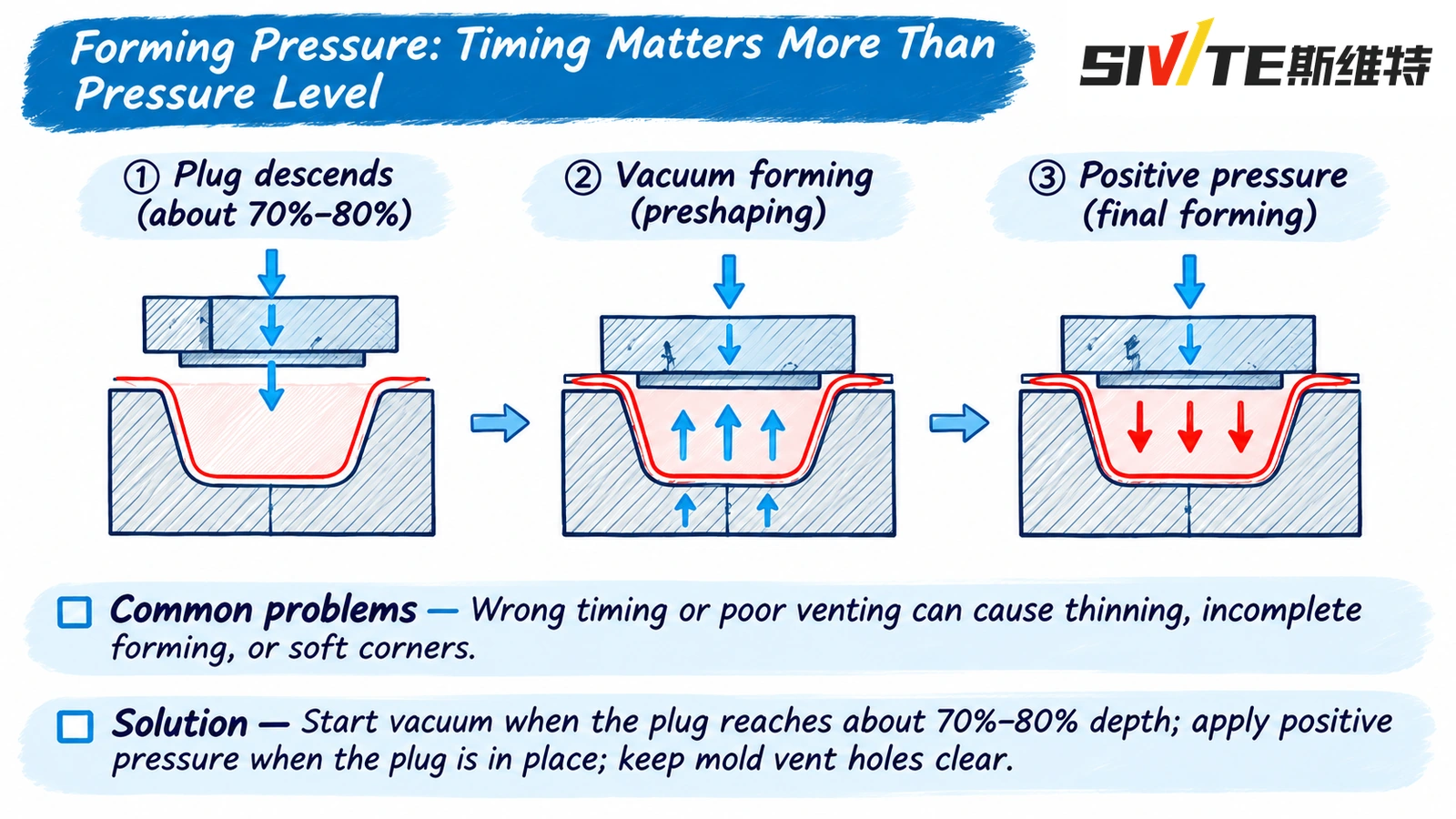
Vacuum forming can only ever apply one atmosphere of differential pressure, about 0.1 MPa. That is enough for shallow draws in hot sheet, and it is why vacuum forming is cheap and forgiving. It is not enough to reproduce fine texture, sharp radii or tight tolerances in a sheet that is at the lower end of its forming window.
Pressure forming applies compressed air on the sheet side, typically 0.3 to 0.7 MPa, and uses vacuum underneath to evacuate the cavity. The higher differential pushes the sheet into detail that vacuum alone cannot reach, and it allows forming at a slightly lower sheet temperature, which shortens cooling. Pressure-assisted vacuum forming sits between the two: a modest air pressure on top, full vacuum below, used when vacuum alone leaves soft detail but full pressure would mark the sheet.
Reading the pressure curve instead of the peak value
The peak pressure number on the recipe screen is the least informative value in the whole process. What matters is the curve: how fast vacuum builds, whether it holds while the sheet is still moving, and whether pressure is released before the part has frozen. A fast vacuum ramp with a short hold can leave the sheet still drawing when the valve closes, which shows up as inconsistent detail from cycle to cycle. Log the curve for a known-good cycle and compare against it when a defect appears — a changed curve usually identifies a leaking seal, a blocked vent or a sticking valve faster than any visual inspection.
Venting and why pressure fails at the mold surface
Every cavity contains air that has to leave before the sheet can touch the surface. If venting is inadequate, the trapped air cushions the sheet, and no amount of additional forming pressure will reproduce the detail — the pressure simply compresses the air instead of pushing the polymer. Vent sizes of roughly 0.5 to 1 mm, sintered plugs in textured areas, and a vent at the deepest point of each cavity are the usual fixes. On deep draws, staged venting — evacuating through the periphery first, then the base — prevents the sheet from sealing off the remaining cavities before they are evacuated.
4. Mold Temperature: The Control Most Often Left Unmanaged
How mold temperature drives shrinkage and cycle time
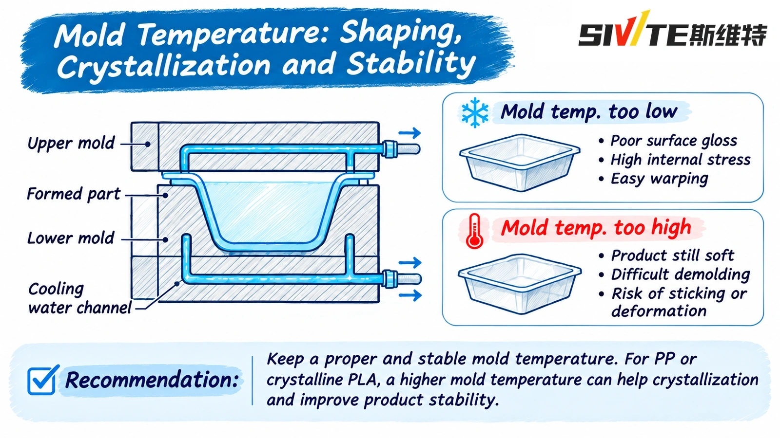
Mold temperature is the only control that sets both dimensional outcome and cycle economics, which is why leaving it to whatever the chiller happens to deliver is expensive. A hotter mold lets the sheet relax more before it freezes, which reduces internal stress and warpage, and produces more consistent shrinkage — but it lengthens cooling, and cooling is usually the largest single share of the cycle. A colder mold shortens the cycle and increases residual stress, warpage and read-through. Typical aluminum tooling for PS and PVC runs around 40 to 80 °C; PET and PP usually need higher mold temperature, in the region of 80 to 120 °C, to keep shrinkage predictable.
Zone control on multi-cavity and large-area molds
On a large or multi-cavity mold the average mold temperature is almost meaningless. The cavity nearest the inlet is colder, the far corner is hotter, and the difference between them shows up as parts that measure differently depending on which cavity they came from. Independent zone control with a measured temperature at each zone — not a single return-line probe — is the only way to make the tool repeatable. Record zone temperatures with the recipe; when a zone drifts, the parts from that cavity drift with it long before anyone notices on the bench.
Cooling-related defects: warpage, read-through, stress marks
Three defects are almost always cooling problems rather than forming problems. Warpage comes from an asymmetric temperature gradient through the thickness or across the part, and it is fixed by balancing mold zones and cooling time, not by adding pressure. Read-through — the ghost of ribs or inserts visible on the show surface — appears when the sheet shrinks onto the mold features while still soft; a more uniform, slightly higher sheet temperature and a more even mold temperature reduce it, while extra pressure usually makes it worse. Stress marks and whitening at corners indicate the sheet was stretched while too cold, or drawn too far in one step.
5. How the Three Controls Interact: A Practical Setting Workflow
Run the sequence below in order on a new mold or a new material. Each step has a condition that must be met before moving on, and each step produces a record you will need later. Expect to spend most of a shift on the first two steps.
- Fix mold temperature and let it stabilize for at least 30 minutes. Record each zone. Do not start heating trials on a mold that is still climbing.
- Set heating time and zone ratio from sheet thickness and material. Start from the material supplier’s window, then adjust zone ratio so that edges and center reach temperature together.
- Measure top and bottom surface temperature and hold the difference within 5 to 8 °C. If you cannot, the problem is the oven, not the recipe.
- Form the first parts with vacuum only, or low-pressure pre-blow. This establishes whether the sheet is drawable at all before pressure is added.
- Increase pressure in steps and log the pressure curve at each step. Stop when detail is reproduced; additional pressure beyond that point adds stress and marking without improving the part.
- Set cooling time from mold temperature and wall thickness, then verify by measuring the part temperature at ejection rather than trusting the timer.
- Confirm the first-off part: dimensions, wall thickness distribution, appearance. Only then lock the recipe.
- Write the parameters to a setup card and add it to the changeover standard. A recipe that lives only in the machine memory is lost at the next power event.
6. Troubleshooting Matrix: Symptom to the Control That Needs Changing
Read the symptom first, then check the control it points to, and change one value per trial. If two changes are made at once and the part improves, you have learned nothing that can be repeated.
| Observed problem | Possible source | First inspection | Corrective action |
|---|---|---|---|
| Webbing between cavities or around corners | Sheet too cold, drawn too fast, or spanning a gap without support | Sheet surface temperature and its uniformity across the sheet | Even out the heating, add or adjust plug assist, pre-stretch the draw |
| Incomplete draw or soft detail | Sheet below its forming window, or air trapped at the mold surface | Sheet temperature at the moment of forming, then venting | Correct the heating first, open or add vents, raise pressure only after both |
| Warpage after ejection | Uneven mold temperature, or the part ejected while still soft | Mold zone temperatures and cooling time | Balance the zones, extend cooling, stop ejecting hot parts |
| Read-through on the show surface | Local hot or cold spots, thick section over ribs or inserts | Mold temperature uniformity and wall thickness over the feature | Even out mold zones and sheet temperature; extra pressure usually makes it worse |
Webbing between cavities or around corners
The sheet stretched as a membrane across a gap instead of drawing into the cavity, which means it was too cold, too fast, or unsupported. Check sheet surface temperature and uniformity first, then add or adjust plug assist, and only then consider raising pressure. Reducing the draw depth in one step by using pre-stretch also helps.
Incomplete draw or soft detail
Detail is missing or rounded. Check that the sheet is above its forming window at the moment of forming, then check venting, then pressure. In that order — pressure is rarely the limiting factor, and raising it on a poorly vented mold only increases cycle time.
Warpage after ejection
The part is flat in the fixture and bows within minutes of ejection. Check mold temperature balance and cooling time, and check that the part is not being ejected while still soft. Higher, more uniform mold temperature with a longer cooling time usually beats any attempt to mechanically straighten the part.
Read-through on the show surface
Ribs, bosses or inserts are visible as ghosting. Check for local hot or cold spots in the mold, sheet temperature uniformity, and the wall thickness over the feature. Increasing sheet temperature slightly and evening out mold zones reduces read-through; increasing pressure typically worsens it.
7. Recording and Standardizing Parameters for Repeatable Production
A setup card is only useful if it records what the next shift actually needs to reproduce the part. At minimum it should carry:
- Material and sheet: grade, thickness, width, supplier batch, and any regrind content.
- Heating: zone temperatures or percentages, dwell time, and measured top and bottom surface temperatures.
- Forming: vacuum and pressure setpoints, the key points of the pressure curve, and plug assist position and timing.
- Mold: measured temperature for every zone, coolant inlet temperature, and flow check.
- Cooling and environment: cooling time, part temperature at ejection, ambient temperature and humidity.
Once the card exists, trend a small number of values rather than auditing the whole recipe. Part weight, a single critical dimension, and one wall thickness measurement per cavity are enough to detect drift weeks before a customer does. When two consecutive trend points move in the same direction, re-run the workflow above instead of adjusting single values on the fly.
Frequently Asked Questions
What sheet temperature should we start with?
Start from the material supplier’s forming window and verify it on your own oven. As a rough guide, amorphous sheet such as PS, PVC and PET forms with a surface temperature in the region of 120 to 170 °C, while PP runs higher and with a narrower window. The number that matters is the measured sheet surface temperature at transfer, not the oven setpoint.
Is higher forming pressure always better?
No. Pressure only has to be high enough to push a correctly heated sheet into the mold detail. Beyond that point it adds stress, can mark the surface, and does nothing for a mold that is not vented properly. If detail is missing, check sheet temperature and venting before increasing pressure.
Why does the same parameter set fail in summer?
Because sheet temperature and cooling rate both depend on ambient conditions. A warmer shop means a hotter sheet arriving at the mold and slower cooling after forming, which shifts shrinkage and cycle time. Recipes tuned in winter often need a seasonal correction; recording ambient temperature and humidity on the setup card is what makes that correction predictable instead of a guess.
How is mold temperature measured correctly?
At the mold surface, per zone, with the mold at operating temperature and after it has stabilized. A single probe on the coolant return line tells you about the chiller, not the cavity. Contact probes or a calibrated infrared unit on the cavity surface, compared zone to zone, is the only measurement that explains why parts from different cavities differ.
Can we shorten cycle time by lowering mold temperature?
You can, and it will shorten cooling — but at the cost of higher residual stress, more warpage and less predictable shrinkage. The cheaper route is usually to improve heat transfer: clean coolant channels, adequate flow, and uniform zone temperatures. Lower the mold temperature only after the tool is thermally balanced, and expect to re-qualify dimensions when you do.
Conclusion: Thermoforming Quality Is a Three-Variable Problem
Heating, forming pressure and mold temperature are not three settings to be optimized one at a time. Mold temperature defines the heat sink, sheet temperature defines what the sheet can do before it reaches that sink, and pressure transfers the shape in the window the other two create. When a part goes wrong, the useful question is not which dial to turn but which of the three has drifted out of balance — and the answer is almost always visible in a temperature measurement someone did not take.
The one habit worth taking away: before changing any value, measure the sheet surface temperature on both faces and the mold temperature in every zone. If those numbers are right and the part is still wrong, the problem is venting, plug assist or tool condition — not the recipe.
SIVITE builds automatic thermoforming machines and sheet extrusion lines, and supports customers on process setup for PET, PP, PS and PVC sheet. If you are qualifying a new mold or transferring a recipe between machines, our engineers can review your heating zones, pressure curve and mold temperature data with you.