Vacuum-vent overflow is one of the most frustrating recurring problems in screw extrusion. The vent is supposed to remove moisture, trapped air, and other volatiles. Instead, molten polymer foams, rises, and escapes through the opening. The result is a dirty machine, unstable output, poor sheet quality, and, in severe cases, an unplanned shutdown.
This condition is commonly described as vent overflow, vent flow, or melt carryover. Regardless of the name, the underlying problem is the same: the vented section has lost the free volume needed for gas to escape.
This guide explains the four most common causes and provides a practical troubleshooting sequence, starting with adjustments that do not require machine disassembly and ending with screw and hardware changes.
Why Does Material Come Out of the Vacuum Vent?
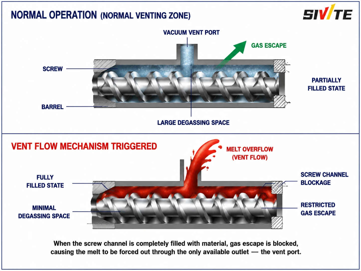
The vacuum vent is positioned over the extruder’s devolatilization or venting section. In a correctly designed and balanced process, this section uses deep screw channels and remains only partially filled. The unfilled channel volume gives moisture and volatiles room to leave the melt and travel toward the vent.
When the pressure balance changes, the local fill level rises. If the screw channel becomes completely filled, the gas path is restricted and melt pressure develops below the opening. The polymer then moves toward the easiest available outlet: the vacuum vent.
The Four Root Causes of Extruder Vent Overflow
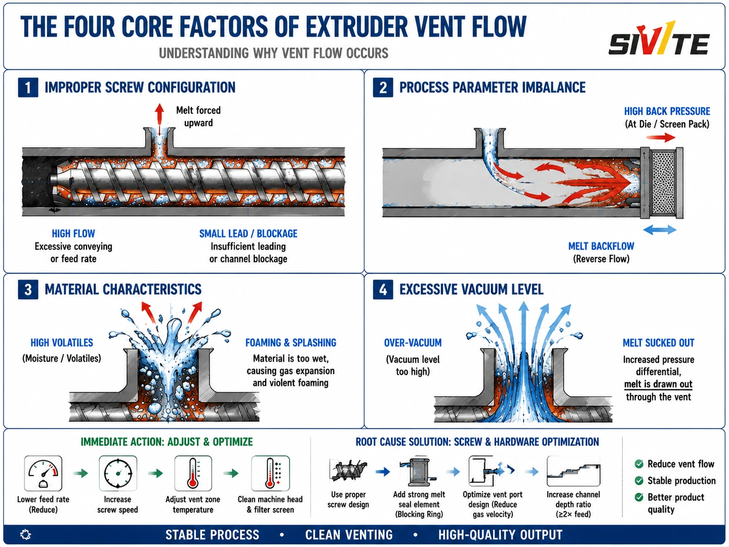
1. Improper Screw Configuration
Reverse kneading blocks, restrictive mixing elements, or reverse-pitch elements are often installed upstream of the vent to establish a melt seal and promote devolatilization. That restriction can be useful, but the material must still be conveyed away from the vent efficiently.
Overflow occurs when the conveying elements at or immediately after the vent have insufficient capacity. Common causes include a lead that is too small, shallow channels, excessive restriction, or a poorly positioned reverse element. Material arrives faster than the downstream section can transport it, the local fill level increases, and melt is forced upward through the vent.
2. Process Parameter Imbalance
Several operating conditions can fill the vent section even when the screw design is fundamentally sound:
- Feed rate is too high. The material throughput exceeds the actual conveying capacity of the screw at the selected speed.
- Barrel temperature is too low. Poorly plasticized material has high viscosity and high flow resistance. Unmelted particles may accumulate near the vent and create a local blockage.
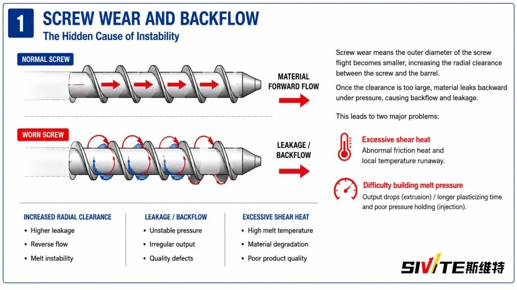
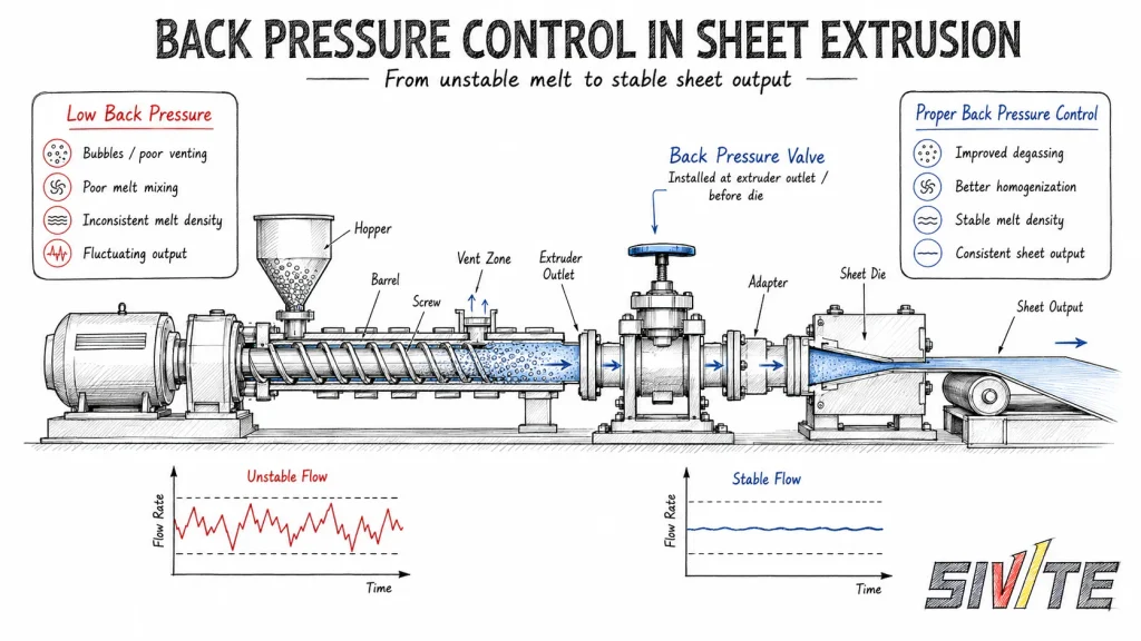
- Die-head pressure is too high. A dirty screen pack, a cold die, or excessive die resistance can generate back pressure and reverse flow, filling the vent section from downstream.
The useful control variable is not feed rate or screw speed alone, but the balance between the two. Throughput must remain below the conveying capacity of the vented section.
3. Material Characteristics
Material condition can intensify vent flow even when the mechanical setup is unchanged.
- High moisture or volatile content produces a large volume of gas as the material heats. Rapid expansion and bubble rupture can carry molten polymer toward the opening, similar to a boiling liquid foaming over a vessel.
- Low melt strength allows bubbles to expand and rupture easily, increasing entrainment.
- Strong barrel adhesion or unstable rheology can disturb forward conveying and promote local accumulation.
Drying requirements, recycled-material content, additives, bulk density, and melt viscosity should therefore be reviewed whenever a new formulation is introduced.
4. Excessive Vacuum
More vacuum does not always mean better devolatilization. Applying maximum vacuum too quickly creates a large pressure differential. Bubbles may expand several times their original volume, and low-viscosity melt can be drawn upward with the gas.
Vacuum should be increased gradually after the process is thermally stable. The correct setting is the lowest vacuum level that achieves the required devolatilization without unstable foaming or melt carryover.
A Practical Troubleshooting Sequence
Start with reversible process adjustments. Change one variable at a time, record the response, and stay within the material supplier’s and equipment manufacturer’s operating limits.
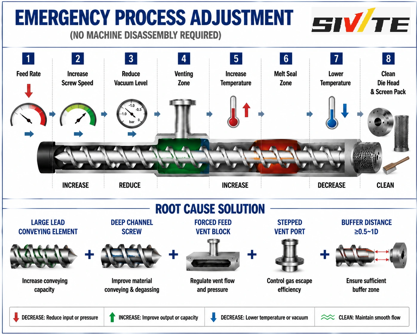
Immediate Process Adjustments: No Machine Disassembly
1. Reduce Feed Rate or Increase Screw Speed
Reduce the feeder output slightly, increase screw speed within the safe operating range, or use a controlled combination of both. The objective is to reduce the local fill level and restore free channel volume below the vent.
Monitor motor load, melt temperature, residence time, and product quality. A higher screw speed is not automatically better if it creates excessive shear heating or unstable feeding.
2. Reduce Vacuum Gradually
Throttle the vacuum valve and observe whether the foaming subsides. For some processes, changing the vacuum from approximately -0.08 MPa to -0.06 MPa can stop carryover with little loss of devolatilization performance. Treat these values as an example, not a universal setpoint.
3. Correct Incomplete Melting
If unmelted particles or hard agglomerates appear at the vent, increase the temperature in the upstream plasticizing zone in small steps. Confirm that the material is fully melted before it reaches the vent.
4. Increase Melt Strength When the Material Is Too Fluid
If the melt is very fluid and foams easily, lower the vent-zone temperature moderately to increase viscosity and melt strength. Avoid overcooling, which can create poor plasticization and make the blockage worse.
5. Reduce Die-Head Back Pressure
Inspect and replace a contaminated screen pack, clean the die head, verify melt-pipe restrictions, and confirm that the die and adapter temperatures are correct. A reduction in downstream pressure often clears vent overflow immediately.
Root-Cause Solutions: Screw and Hardware Optimization
If reasonable process changes cannot create a stable operating window, the screw arrangement or vent hardware may have reached its design limit.
Use High-Capacity Conveying Elements Below the Vent
Large-lead, multi-start, deep-channel conveying elements provide the free volume needed for devolatilization and rapidly transport melt away from the opening. As a practical design target, the local conveying capacity should comfortably exceed the upstream feed capacity; a factor of about two is often used as an initial engineering check and must be validated for the actual material and screw geometry.
Review the Upstream Restriction
Check whether a reverse element, kneading block, or melt-seal element is too restrictive or too close to the vent. A buffer distance of approximately 0.5 to 1 screw diameter between the restriction and the vent is a useful starting point, subject to the screw design and process requirements.
Add a Vent Stuffer or Deflector
A powered vent stuffer, vent plug, or scraper block can return rising melt to the screw while allowing gas to escape. This is especially useful for low-bulk-density, foaming, or high-throughput materials.
Improve the Vent-Port Geometry
A small opening increases gas velocity and can entrain droplets. An enlarged, flared, or stepped vent port reduces gas velocity and gives the melt more opportunity to fall back into the barrel. The vacuum piping and separator must also be sized to avoid restriction and contamination.
Recommended Commissioning Practice
When introducing a new resin or formulation:
- Confirm moisture and volatile content before startup.
- Review melt viscosity, melt strength, bulk density, and drying requirements.
- Start at a conservative feed rate and moderate vacuum.
- Establish complete melting before increasing throughput.
- Increase vacuum gradually while watching the vent.
- Record feed rate, screw speed, temperatures, head pressure, motor load, and vacuum level at the first stable condition.
These records create a reliable baseline for future troubleshooting and make it easier to distinguish material changes from machine problems.
Final Takeaway
Vent overflow can usually be summarized as too much material arriving, too little material leaving, or too much gas expanding.
The fastest diagnosis follows the same order every time: restore free volume below the vent, stabilize melting and vacuum, remove downstream back pressure, and only then revise the screw configuration or vent hardware. A correctly balanced venting section stays partially filled, keeps the gas path open, and produces stable, clean output.