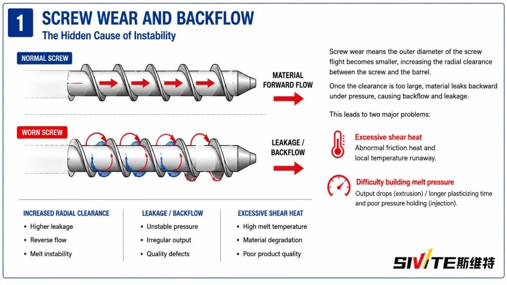
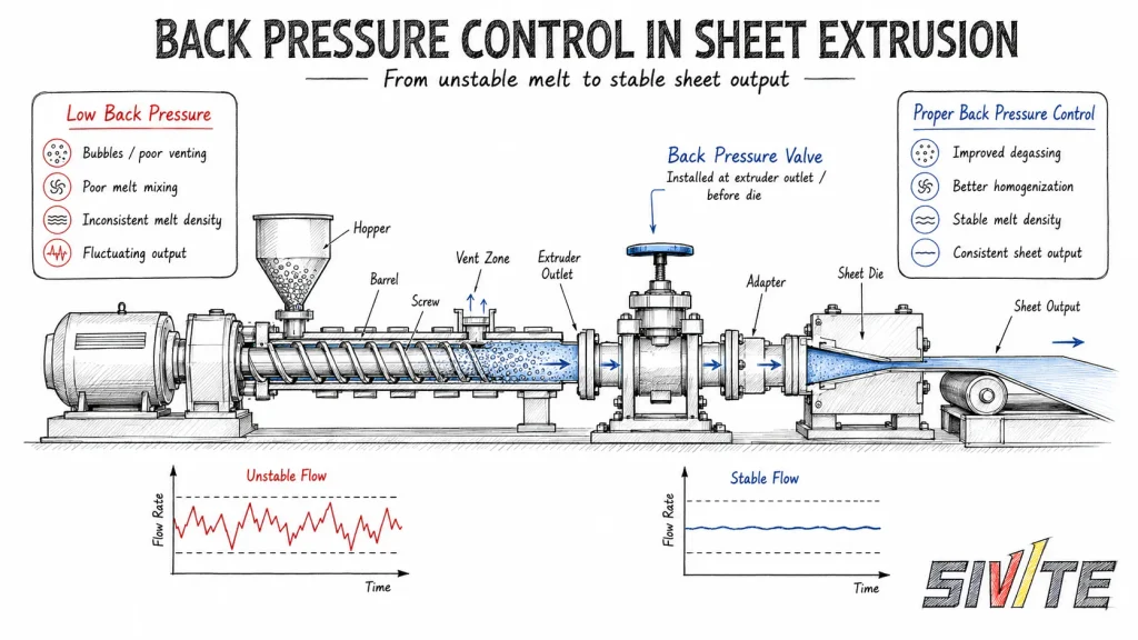
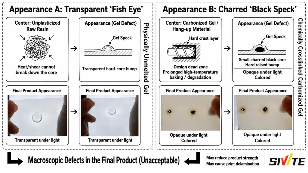
Transverse lines on plastic sheet often look like narrow bands, vibration marks, or bamboo-joint patterns across the sheet width. In many factories, the first reaction is to suspect screw wear or poor screw mixing. That is understandable, but it is not always the right starting point.
In plastic sheet extrusion defects, transverse lines are often caused by mechanical vibration, roller speed mismatch, unstable melt pressure, or local melt fracture at the die lip. Replacing the screw before checking these hidden causes can waste time and money while the original problem remains in the line.
This guide explains how to diagnose extrusion transverse lines in a practical engineering sequence. For the equipment layout and common line configurations, see SWT’s Plastic Sheet Extrusion Line.
How to Diagnose Periodic Stripe Defects, Vibration Marks, and Melt Fracture in Sheet Extrusion
Before disassembling the extruder, first determine whether the defect is periodic, process-related, or surface-shear related. The key is to observe the stripe spacing, machine frequency, melt pressure trend, and surface appearance.
A useful first check is simple:
- If the line spacing is very regular, check mechanical vibration and transmission parts first.
- If the stripe changes with roller speed or haul-off tension, check the calender and downstream drive.
- If the sheet surface becomes rough, dull, or micro-waved near the die, check shear stress and melt fracture.
This method keeps sheet extrusion troubleshooting focused. It also helps avoid unnecessary screw replacement when the real cause is outside the screw barrel.
1. Mechanical Gear Vibration: The Hidden Source of Periodic Transverse Lines
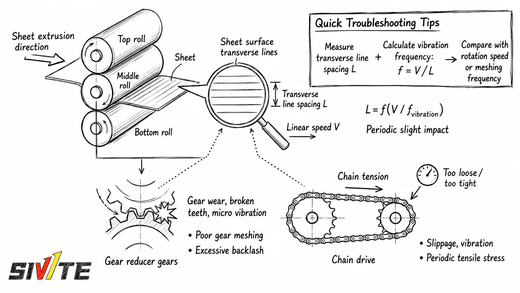
One of the most overlooked causes of transverse stripes is micro-vibration from the three-roll calender, gearbox, chain drive, bearings, or transmission couplings.
When a gear tooth is worn, a chain is too loose, a reducer has backlash, or a roller bearing is unstable, the sheet receives a small repeated impact. The defect then appears as regular transverse lines across the sheet surface.
The important feature is frequency. If the line spacing is consistent, measure the distance between two adjacent stripes and compare it with roller speed, gear meshing frequency, or chain rotation frequency.
The relationship is:
- Line spacing becomes shorter when sheet speed increases and vibration frequency stays constant.
- Line spacing may match a gear, chain, roller, or bearing cycle.
- The defect can appear even when the extruder melt itself is stable.
For calender-related products and sheet take-off arrangement, the Three Roll Calender System should be checked together with the downstream drive system.
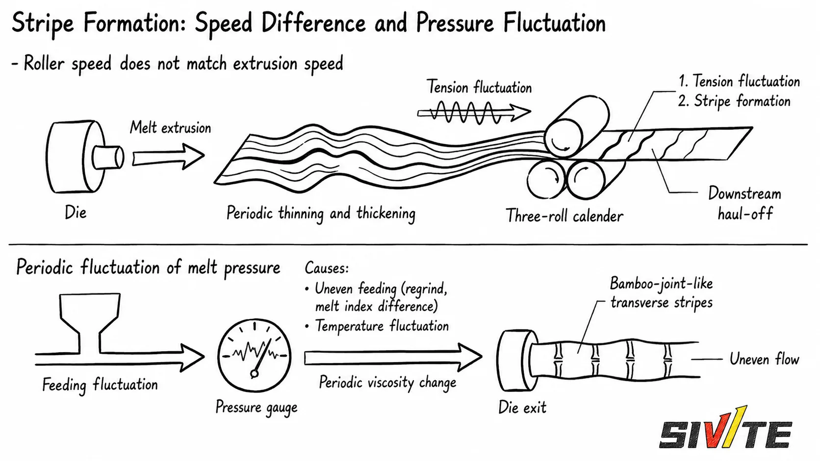
2. Roller Speed Mismatch and Melt Pressure Fluctuation
Another common source of transverse lines is a mismatch between die output, roller speed, and downstream haul-off speed.
In sheet extrusion, the melt exits the die as a continuous curtain or sheet. The calender and haul-off must pull this melt at a stable rate. If the roller speed is slightly too fast or too slow, the sheet may alternately stretch and relax. This creates periodic thinning and thickening, which becomes visible as transverse lines.
At the same time, unstable melt pressure can create the same visual result. Feeding fluctuation, poor drying, inconsistent regrind ratio, temperature fluctuation, or die resistance changes can cause the flow rate to rise and fall. The sheet then leaves the die with uneven flow, producing bamboo-like transverse patterns.
When checking this type of defect, record:
- Melt pressure at the die or adapter
- Screw speed and feeding stability
- Three-roll speed and haul-off speed
- Sheet thickness trend
- Whether the stripe frequency changes after speed adjustment
If the defect follows melt pressure movement, the problem is not only mechanical. It may be related to material feeding, screw conveying stability, die resistance, or upstream venting. Existing extrusion process issues such as vent instability can also disturb pressure; see this Extrusion Troubleshooting Guide.
3. Excessive Shear Stress and Melt Fracture
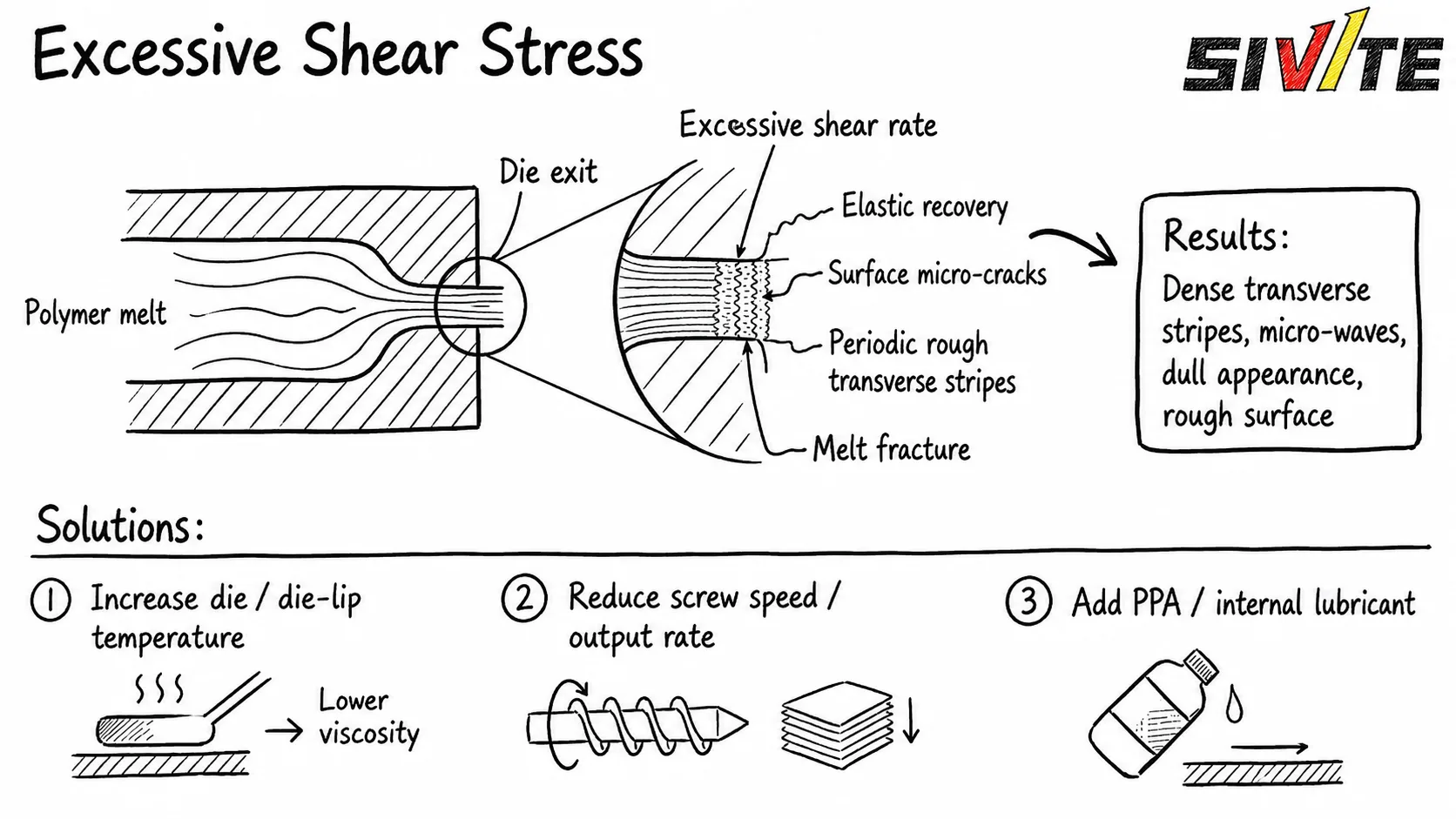
If transverse lines are dense, rough, dull, or wave-like, the cause may be melt fracture instead of mechanical vibration.
Melt fracture occurs when the polymer melt experiences excessive shear stress at the die lip. The melt is forced through a narrow die gap at high speed. When the shear rate exceeds the material’s stable flow limit, the melt surface loses smooth flow and releases elastic stress after leaving the die.
The result can include:
- Rough surface
- Dense transverse stripes
- Micro-waves
- Dull appearance
- Local surface cracking
This problem is often seen when output is too high, die temperature is too low, die lip gap is too narrow, or the material has high viscosity. It can also appear when additives, fillers, or recycled materials change the melt flow behavior.
For PET sheet, temperature control, drying, viscosity stability, and die conditions are especially important. See the PET/PLA configuration on the PET Sheet Extrusion Process page for the related production line context.
Typical solutions include:
- Increase die or die-lip temperature gradually.
- Reduce screw speed or output rate.
- Check whether the die lip gap is too narrow.
- Improve melt filtration and material cleanliness.
- Add PPA or an internal lubricant when the material system allows it.
The screw should still be checked, but it is only one part of the system. A suitable Extruder Screw Design must work together with the die, filter, adapter, and downstream calender.
4. Fast Troubleshooting Guide for Transverse Lines
When transverse lines appear, avoid changing many parameters at once. Use a step-by-step diagnosis:
Step 1: Confirm Whether the Stripe Is Periodic
Measure the distance between repeated lines. If spacing is stable, compare it with roller speed, gear speed, chain cycle, and bearing rotation.
Step 2: Check Mechanical Transmission
Inspect gear reducer condition, coupling alignment, roller bearing noise, chain tension, and backlash. A small repeated vibration can leave a clear mark on the sheet.
Step 3: Check Roller and Haul-Off Speed
Slight speed mismatch can create repeated stretching and relaxation. Adjust roller speed carefully and watch whether the stripe spacing changes.
Step 4: Check Melt Pressure Stability
Observe whether pressure rises and falls in the same rhythm as the defect. If it does, check feeding stability, material consistency, filter blockage, temperature zones, and die resistance.
Step 5: Check Die Shear and Melt Fracture
If the sheet surface is rough or dull, reduce shear stress. Increase die temperature gradually, reduce output if necessary, and inspect the die lip.
Step 6: Inspect the Screw Last
Only after the mechanical, pressure, and die-lip checks are complete should the screw be removed for inspection. This saves downtime and avoids replacing parts that are not the root cause.
Conclusion: Diagnose Before Disassembling
Transverse lines in sheet extrusion are not always caused by the screw. In many cases, the real source is hidden in the three-roll calender, transmission system, roller speed matching, melt pressure stability, or die-lip shear stress.
For stable sheet quality, troubleshooting should follow the actual defect pattern. Regular stripes point to mechanical frequency. Thickness waves point to speed or pressure fluctuation. Rough dense surface marks point to melt fracture.
Before replacing the screw, check these three hidden causes first. It is a faster and more reliable way to solve extrusion surface defects and improve production stability.
Related Equipment
Sheet Extrusion Lines
For PET, PP and PS sheet production, review the extrusion configurations and engineering options relevant to this technical topic.
View Sheet Extrusion LinesDiscuss your application on WhatsApp